• We are currently upgrading MFK. thanks! -neo

It’s been a whole year

After I welded in these rails for the battery box I discovered the frame had a lot of weld draw that was sucking in the rails.

I did cut those battery box rails and the frame did spring apart but only about 3/16” and I was expecting it to spread over 3/8”.

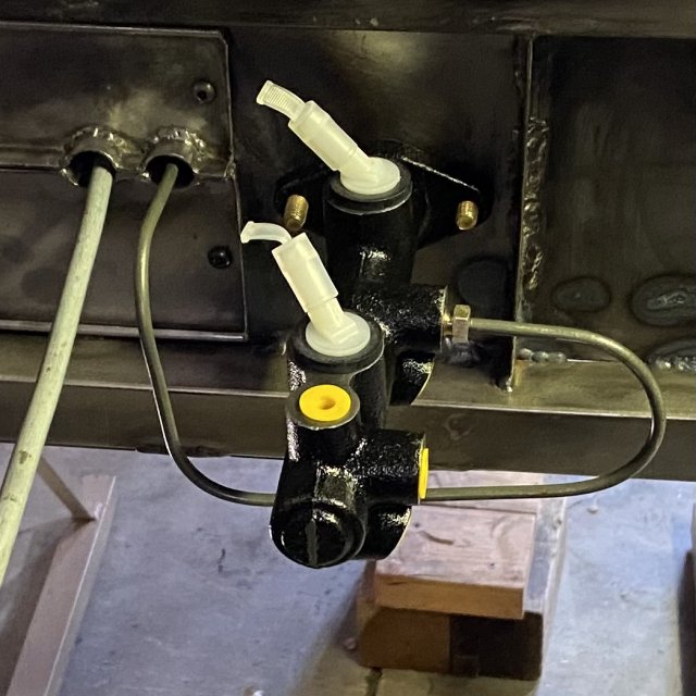
Well at this point it is what it is and that’s where it’s going to stay. Meanwhile I had to get the rear brake line out of my way so I mocked up the master cylinder and bent the brake line to fit. I cut the fuel line. It will have a filter right below there.
3098E0BB-08F8-458F-AF79-495558D8EB01.jpeg

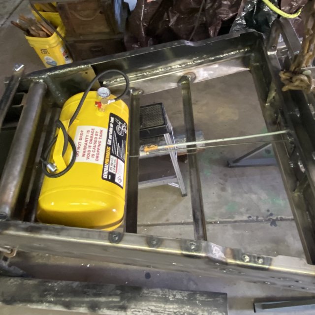
Since the laws in California have changed, finding the racing fuel tank of my dreams at Amazon is hopeless. They won’t deliver it to California.

Anyhow I did find some fuel tanks that they would deliver but not in the shape that I need. I was hoping to get a dragster style tank in this size and shape: A 5 gallon cylinder. This harbor freight tank is a pressure tank and it is very heavy by comparison. Here you can see the two rails I welded in to support the batteries, and if you look closely you can see I cut them in the middle.
9D19FD97-F6DC-4644-89D2-8F228161DCF0.jpeg

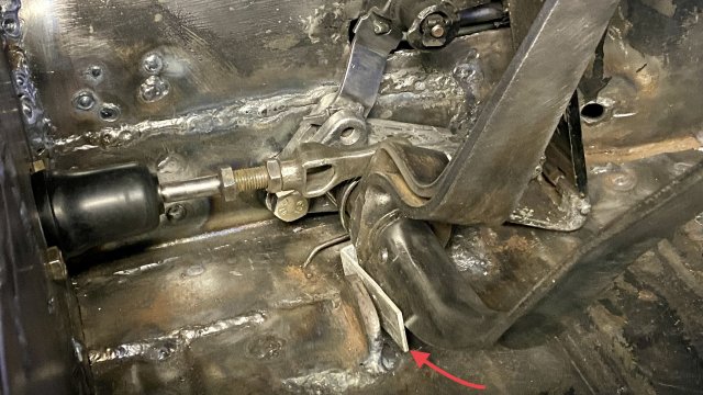
I did get the pedal assembly mostly cleaned up, and mounted with cables, spring, etc. Everything clears and operates smoothly enough.
6ACDD81F-BFB0-4875-A7D0-7AB982F9A0A1.jpeg
But the arrow in my pic shows where I stuffed a shim in the pedal stop to make things line up.

I need to made some real pedal stops.

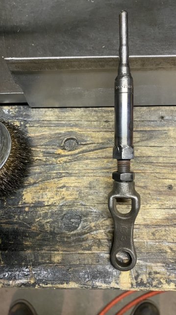
Also the brake pushrod needs to be 2 inches longer.
 
The pushrod is lengthened, the pedal stop is welded in, & the new hydraulic tubes are flared.
52C7FBD6-E145-498F-A4B5-DCABB0A89C30.jpeg

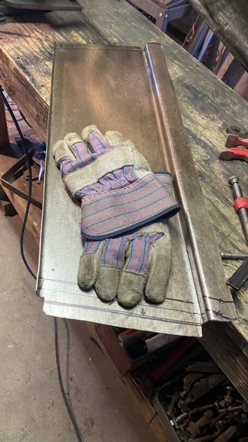
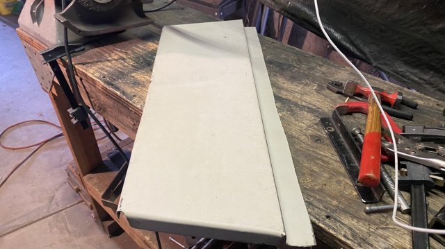
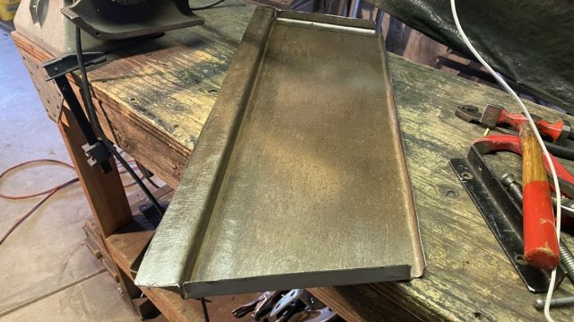
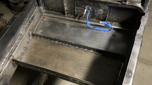
I formed up two floor pans from some recycled sheet metal, and got them welded in on top.

6F705440-D0C5-45E6-BA90-73C98FBF6DD4.jpeg

3162C582-CF3D-4E63-A37D-F4EEF0EC144B.jpeg
9E3A1FDC-5491-4E4F-B2BB-9116BB10AACD.jpeg

250A1AFB-E093-4EBC-A75C-BCB0716A4AA5.jpeg


B3DC6B60-880F-4B87-8798-252F141FA1FB.jpeg

EDFB1CE1-52C5-4727-9718-1DB40D74E8D2.jpeg

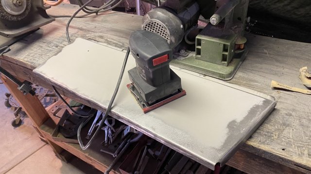
The paint on these was totally incompatible with what I’m shooting so I had to strip them to bare metal.

30F37F5C-F198-4197-B95E-C2E4822D891B.jpeg

Each panel has about 50 tiny welds on this side. I’ll have to flip the frame again, to them in weld on the bottom.

AF14BD3C-FFE8-4B16-8F5C-A1EE70132B0E.jpeg

Trying to come up with some seat rails & a seat mounting plan.

F924CA59-9D0A-4A8E-8B34-A12C5936BF9B.jpeg
 
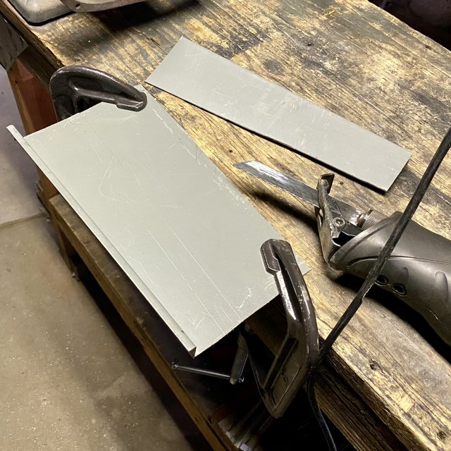
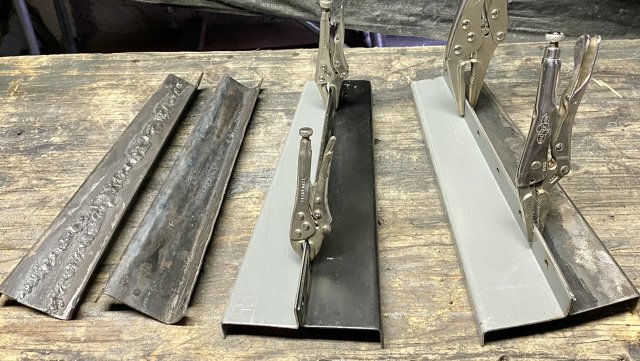
I made two new 14 gage seat risers to replace the ones I boogered up.

7764D764-3867-4F82-A9B1-029F41440337.jpeg

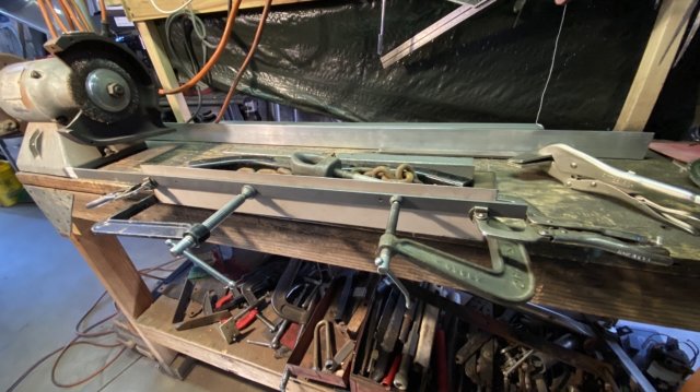
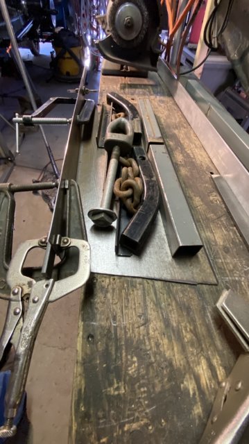
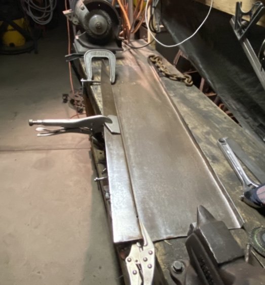
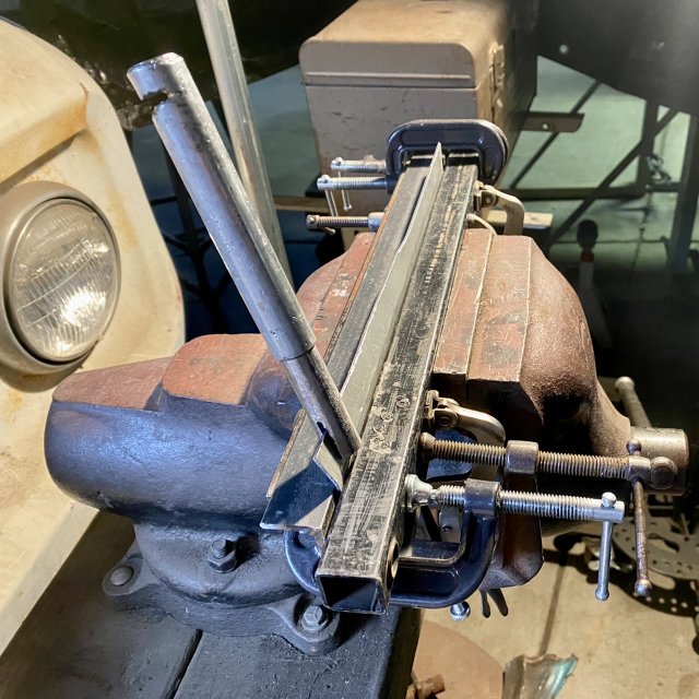
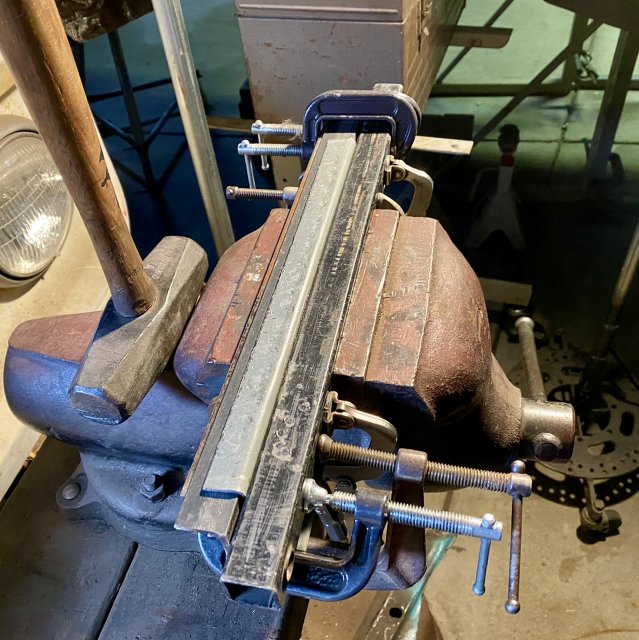
I don't have a press or brake, so I made the flanges by hand, with a vice and clamps.
4600269D-5E87-413B-8247-4210590B72B2.jpegAnd a 4 lb hammer.
CF275687-89ED-4A57-A51F-1DDD1ABE3729.jpeg

Here you see the nicly matched pairs. Also the original two I “ reversed”.
4ADEF7A6-D388-4C76-8B57-278C28065CF4.jpeg

This kit had four left hand risers and no right hand ones. Sonebody at the factory screwed up, but the original builder used them anyhow, resulting in the seats being mounted crooked.

When I originally discovered this, I reversed two of the brackets with torch and hammer. One I cut and welded, but the real ugly one was just heated and beat over an anvil.

I was in a hurry to get the car registered then.
Now, 4.5 years later, I am not in a hurry. No need to even try.
 
Well this was a minor screwup.

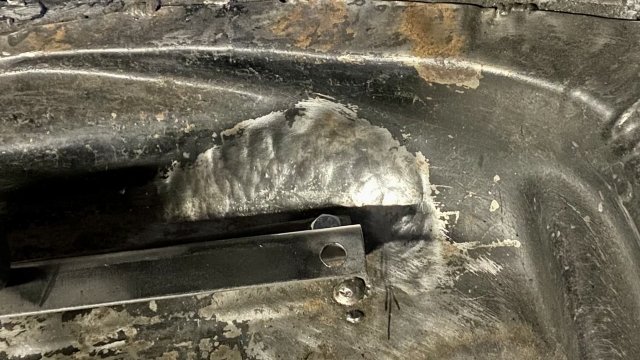
When I put those two panels into the floor I did not put any stiffening ridges or beads on them. One of them has three flanges and it stayed level but the one that only has a single flange will “oil-can”. You can push on it with your finger and it will pop back-and-forth.

So now I either have to weld a stiffner to that panel or put some kind of embossments in it which will suck up the “extra” metal. A panel will oil-can because it is actually slightly too large for its constraints at the edges.

It was not physically too large, you understand, But as I welded it in 50 places edge constraints developed under conditions of uneven thermal expansion. When everything cooled off it wasn’t tight.

However, I still haven’t flipped the frame over to weld this panel on the bottom and that will change the constraints once again. We will see what happens there before I try to emboss the panel.
 
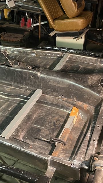
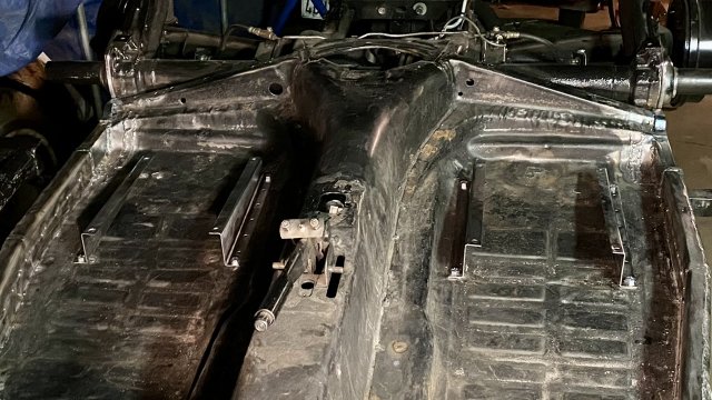
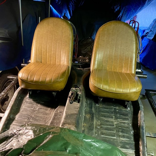
I did some more work on the seats, getting them set up to weld in the seat bases. There is an issue with fitment, as the floor pan rises at the rear inner corner of the seats.

Instead of modding the risers, I just flattened the floor with hammer and dolly.

80B9F91A-E412-42FE-8EA0-28F8130CFA1B.jpeg


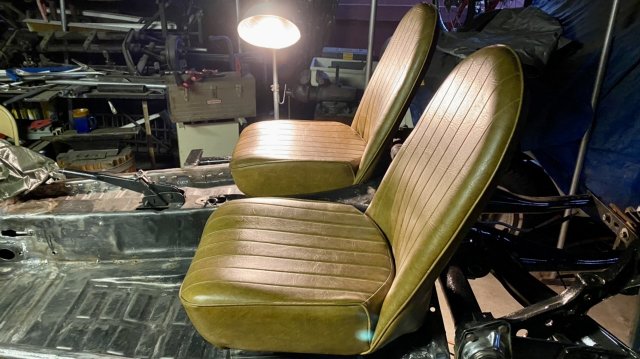
I got the seat risers installed and the seats fitted.

7617C265-CA6A-4942-BFA0-1958C1CEAB8D.jpeg

Then the seats came back off during welding & paint.
8DD8F5F5-0485-47DA-A8FA-9F54B5031D87.jpeg

32995E4D-B450-4F78-904C-D7E590D2837F.jpeg

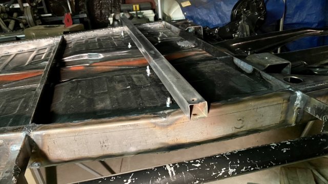
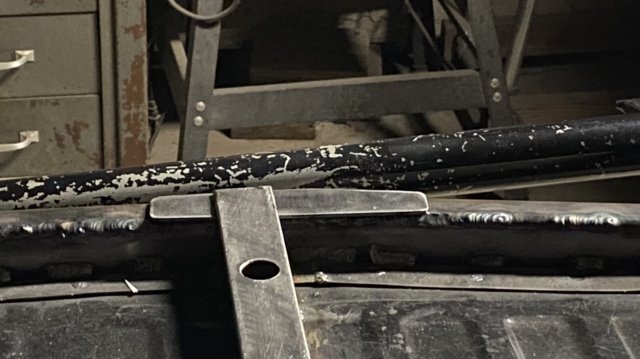
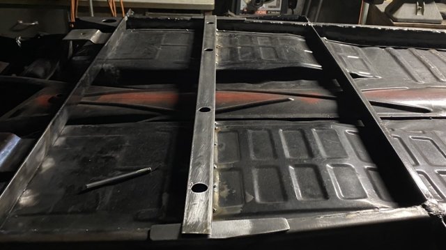
The back of the seats bolt through the steel crossmember, but the fronts just bolt to the pan. This was flimsy & always needed its own crossmember.
FAF71DEF-4B69-42F8-BCF1-CB2784979A39.jpeg
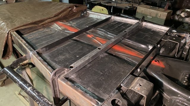
This new crossmember tube is only 16ga so just enough to stiffen the floor.

30225BE2-03C2-4072-BD59-14CAA408597D.jpeg
 
D42A1ADA-2475-4691-982E-276D2E174DC1.jpeg
So the crossmember didn’t fit quite right. Twice.

I got it drilled, made the access holes, and bolted it in, but it still needs a third trimming.

I’ll take a bit more off the edges and then it gets welded in.
 
I know absolutely nothing about restoring or rebuilding cars, but I just love these step-by-step updates. I am amazed and fascinated by your project!
 
  • Love
Reactions: Ulu
Well today was a challenge. I tried to weld that crossmember in, and started masking a real mess.

When TIG welding steel you see the blue-white plasma flame of the electric arc, and you see the glowing puddle of hot liquid metal.

When you TIG weld over dirty or painted steel you will also see miniature fireworks. Tiny little orange sparks fly from the puddle. This is carbon atoms as they burn up and die.

But my metal was clean. Burnished and acid dipped, then sanded. I had a new electrode.

What the devil?

You will also see those sparks when you are welding and run out of argon. But I had a fresh bottle. I had just turned it on.

I checked the flow, and gas was flowing normally. I even added more gas. The sparks actually increased a bit. My weld looked like porous crap. I did a test weld on different steel. Same issue…

Finally, you will see those little sparks when someone has put MIG welding gas in an argon bottle: 25% argon and 75% CO2.

The carbon sparks come from the CO2.

So after I figured this out, I had to take the gas back to the welding shop and exchange it. This whole exercise blew most of my energy today and I didn’t get as much done as I expected.

I did however get 24 little welds tying that crossmember to the floor pan, and the whole car just got much quieter and stiffer.
 
Hmmm.. For some reason I cannot edit my words here on this forum.

MIG gas is actually 75% argon and 25% CO2. Not the opposite as I have stated.
 
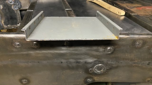
The new crossmember is welded in, and I have made the little gussets for each end, where the frame bends.

A517A1C8-86E0-4C05-815C-97F7DDFA29DF.jpeg

2FB434A5-3442-4B30-A629-E7854162C067.jpeg

Those are not welded down yet.

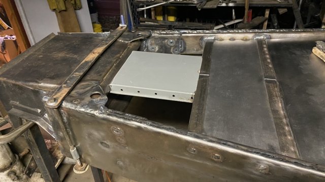
I also made this support for the fuel tank cradle and fitted it in.

D417A72D-9F75-41D5-B976-BD72A889E56F.jpeg

AC022AC9-FBF9-450C-BDBF-C39BDB2DADB6.jpeg

I should get this stuff all welded in today.
 
Back
Top